Single Cylinder 4 Stroke Engine Diagram

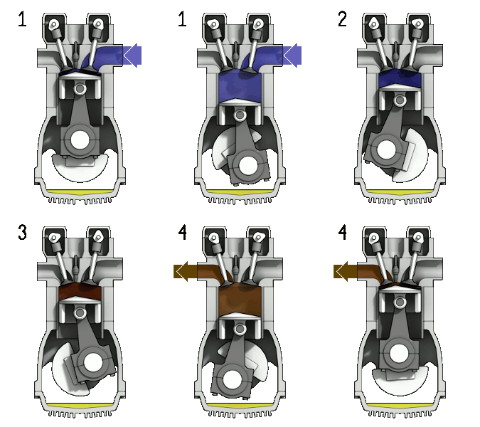
Figure 1. 4-stroke internal combustion engine. 1:fuel injection, 2:ignition, 3:expansion(work is done), 4:exhaust.[1]
The four-stroke engine is the most common types of internal combustion engines and is used in various automobiles (that specifically use gasoline as fuel) like cars, trucks, and some motorbikes (many motorbikes use a two stroke engine). A four stroke engine delivers one power stroke for every two cycles of the piston (or four piston strokes). There is an animation to the right (Figure 1) of a four-stroke engine and further explanation of the process below.
- Intake stroke: The piston moves downward to the bottom, this increases the volume to allow a fuel-air mixture to enter the chamber.
- Compression stroke: The intake valve is closed, and the piston moves up the chamber to the top. This compresses the fuel-air mixture. At the end of this stroke, a spark plug provides the compressed fuel with the activation energy required to begin combustion.
- Power Stroke: As the fuel reaches the end of it's combustion, the heat released from combusting hydrocarbons increases the pressure which causes the gas to push down on the piston and create the power output.
- Exhaust stroke: As the piston reaches the bottom, the exhaust valve opens. The remaining exhaust gas is pushed out by the piston as it moves back upwards.
The thermal efficiency of these gasoline engines will vary depending on the model and design of the vehicle. However in general, gasoline engines convert 20% of the fuel (chemical energy) to mechanical energy—in which only 15% will be used to move the wheels (the rest is lost to friction and other mechanical elements).[2] One way thermodynamic efficiency can improve in engines is through a higher compression ratio. This ratio is the difference between the minimum and maximum volume in the engine chamber (seen as TDC and BDC on figure 2). A higher ratio will allow a larger fuel-air mixture to enter, causing a higher pressure, leading to a hotter chamber, which increases thermal efficiency.[2]
The Otto Cycle

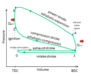
Figure 2.The real otto cycle process that occurs in a four stroke engine.[3]

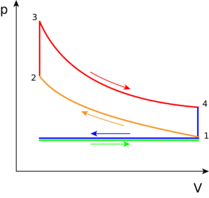
Figure 3. The ideal Otto Cycle.[4]
The pressure volume diagram (PV diagram) that models the changes the fuel-air mixture undergoes in pressure and volume in a four stroke engine is called the Otto cycle. The changes in these will create heat, and use this heat to move the vehicle or machine (hence why it's a type of heat engine). The Otto cycle can be seen in Figure 2 (real Otto Cycle) and Figure 3 (ideal Otto Cycle). The component in any engine that uses this cycle will have a piston to change the volume and pressure of the fuel-air mixture (as seen in Figure 1). The piston gains motion from combusting the fuel (where this happens is explained below), and an electric boost at the start up of the engine.
The following describes what occurs during each step on the PV diagram, in which the combustion of the working fluid—gasoline and air (oxygen), and sometimes electricity, changes the motion in the piston:
Real cycle-step 0 to 1 (ideal cycle-green line): Referred to as the intake phase, the piston is drawn down to the bottom to allow the volume in the chamber to increase so it can "intake" a fuel-air mixture. In terms of thermodynamics, this is referred to as an isobaric process.
Process 1 to 2: During this phase the piston will be drawn up, so it can compress the fuel-air mixture that entered the chamber. The compression causes the mixture to increase slightly in pressure and temperature—however, no heat is exchanged. In terms of thermodynamics, this is referred to as an adiabatic process. When the cycle reaches point 2, it is when the fuel is met by the spark plug to be ignited.
Process 2 to 3: This is where combustion occurs due to the ignition of fuel by the spark plug. The combustion of the gas is complete at point 3, which results in a highly pressurized chamber that has lots of heat (thermal energy). In terms of thermodynamics, this is referred to as an isochoric process.
Process 3 to 4: The thermal energy in the chamber as a result of combustion is used to do work on the piston—which pushes the piston down—increasing the volume of the chamber. This is also known as the power stoke because it is when the thermal energy is turned into motion to power the machine or vehicle.
Purple line (Process 4 to 1 and exhaust phase): From process 4 to 1 the exhaust valve opens and all the waste heat is expelled from the engine chamber. As the heat leaves the gas, the molecules lose kinetic energy causing the decrease in pressure.[5] Then the exhaust phase (step 0 to 1) occurs when the remaining mixture in the chamber is compressed by the piston to be "exhausted" out, without changing the pressure.
For Further Reading
- Internal combustion engine
- Otto cycle
- Two stroke engine
- Thermal efficiency
- Or explore a random page
References
- ↑ Wikimedia Commons [Online], Available: https://upload.wikimedia.org/wikipedia/commons/d/dc/4StrokeEngine_Ortho_3D_Small.gif
- ↑ 2.0 2.1 R. Wolfson, Energy, environment, and climate. New York: W.W. Norton & Company, 2012, p. 106.
- ↑ Actual and Ideal Otto Cycle - Nuclear Power", Nuclear Power, 2018. [Online]. Available: https://www.nuclear-power.net/nuclear-engineering/thermodynamics/thermodynamic-cycles/otto-cycle-otto-engine/actual-and-ideal-otto-cycle/. [Accessed: 22- Jun- 2018].
- ↑ Wikimedia Commons [Online], Available: https://en.wikipedia.org/wiki/Otto_cycle#/media/File:P-V_Otto_cycle.svg
- ↑ I. Dinçer and C. Zamfirescu, Advanced power generation systems. London, UK: Academic Press is an imprint of Elsevier, 2014, p. 266.
Posted by: romonaromonamichale0267943.blogspot.com
Source: https://energyeducation.ca/encyclopedia/Four_stroke_engine
Post a Comment for "Single Cylinder 4 Stroke Engine Diagram"